HIPPS CONCEPT
Definition & Philosophy
HIPPS is the acronym for High Integrity Pressure Protection System. Main function of HIPPS is an independently instrum whose function is to protect an installation from the overpressure produced in the high pressure part of the same, isol pressure part from it.
Idea of HIPPS is to be used instead of traditional safety systems such as relief devices with four main advantages:
- Environment protection: relief systems release the service fluid to the atmosphere which while HIPPS avoid flui released out of the system keeping the environment free of emissions.
- HIPPS have to be a safety level equal or higher than the traditional relief methods; calculated safety levels show to be ten times more reliable than traditional methods.
- Creating a frontier between two parts of the installation allows the downstream part of the valves of the HIPP lower pressure and therefore, to reduce the cost of pipes and related pressure equipments installed on that part.
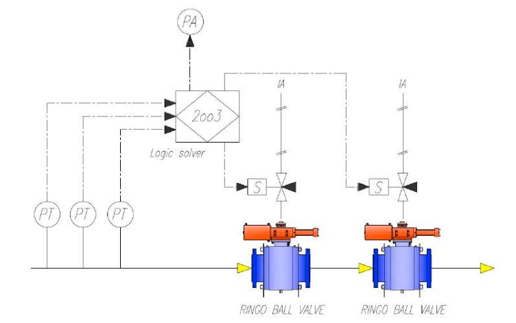
Hipps Scheme
The complete HIPPS consist of several elements that are detailed below:
- Initiators (Pressure Transmitters). HIPPS are typically supplied with three pressure transmitters that monitor the the line and provide the information to the next element.
- Logic Solver: it receives the information from Pressure Transmitters and it is configured to send the signal to op final elements, when the received input is above the preconfigured pressure value.
- Final elements: Final elements have the function of isolating the downstream part of the installation from the o Typically, final elements consist of two valves with their related actuators installed in serial to be closed when received from the logic solver.
APPLICABLE STANDARDS AND SAFETY INTEGRITY LEVEL
HIPPS are designed according to following standards:
- IEC 61508: “Functional Safety of Electrical/Electronic/Programmable Electronic Safety Related System”.
- IEC 61511: “Functional Safety: safety instrumented systems for the process industry sector”.
- ANSI/ISA S84.01: “Application of Safety Instrumented Systems of the Processed Industries”.
Standards mentioned above are performance based so design of HIPPS is also based on the required Safety Integrit SIL has four categories, from 1 to 4, and it is defined by plant end user by means of making a risk analysis of the p related to the fulfillment of the tolerance risk: this means that SIL level results of the combination of two factors:
- Frequency of fail occurrence.
- Consideration of the consequences of fail (dangerous failure or safe failure).
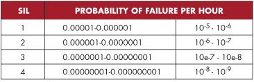
Safety Instrumented Function (SIF) defines the level of protection against failure and it is defined by the Probability o Demand (PFD). PFDavg is defined as the average probability of failure the safety function between 0 to 1. Standard defines the maximum allowable PFDavg value depending how often the demand of SIF is:
- High demand: safety demand interval shorter than one year.
- Low demand: safety demand interval longer than a year.
SIL Level is related to a this PFDavg value and must be considered for the complete functional loop, all its elements an between them.
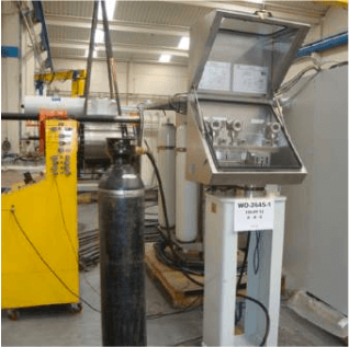
SAMSON RINGO HIPPS IS PROVIDED
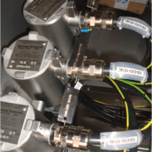
Initiators (pressure transmitters)
HIPPS are typically supplied with three pressure transmitters that monitor the pressure in the line and provide the information to the next element. This three elements can be selected from the same supplier or three different ones; supplying the pressure transmitters of three different brand avoid what it is call a “common fail”, for instance a quality problem in a lot of Pressure Transmitters produced by the same manufacturer that could affect to the proper performance of the HIPPS.
HIPPS is designed to be able work only with two Pressure Transmitters for a while. This is to allow to make some checking or to replace any of them with the HIPPS under operation. In such case, system is working in “degraded mode” and logic solver receives that information.
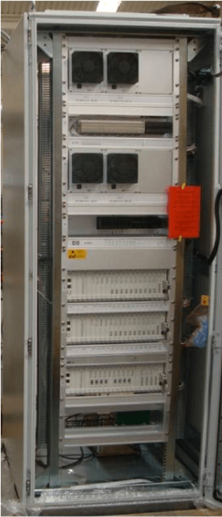
Logic Solvers
Logic solver is the device in charge of processing the input signals received from the initiators and it is configured to send the signal to operate the final elements, when the received input is above the preconfigured pressure value.
Ringo can supply HIPPS with different types of logic solvers:
- Central Processing Unit (CPU): software can be programmed to configure the response based on the inlet signals. This type is certified up to SIL 3.
- Solid State Logic (SSL), with a configuration of intelligent cards. This type cannot be programmed but can be certified up to SIL 4
Logic Solver can be supplied with different configurations, based on customer specifications. Cabinets with IP protection grade for hazardous area are available. Interface with the user are customized, by instance touch screen or light and push bottoms panel.
Logic solvers can be supplied to support any communicating protocol:
- Mod bus, OPC, Profibus, Send and Receive TCP & HART.
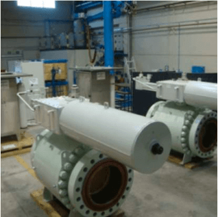
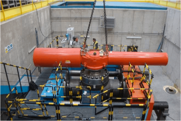
Final Elements
Final elements have the function of isolating the downstream part of the installation from the overpressure. Typically, final elements consist of two valves with their related actuators installed in serial to be closed when the signal is received from the logic solver. Actuators may be pneumatic or hydraulic and are supplied with their own control panel, including the solenoid valves to govern their operation. Actuators are sized to provide a very fast operation time (less than 2 seconds). Samson Ringo offers two type of valves for HIPPS: Ball and Axial.
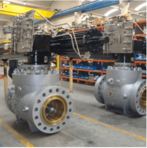
Valves
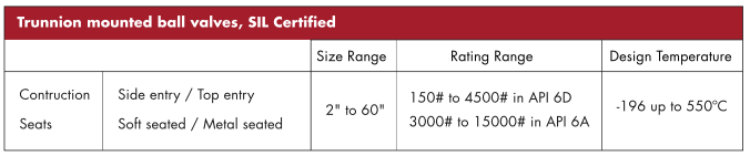
Ball Valves
Ringo Válvulas offer a full range of trunnion mounted ball valves designed and produced according to API 6D/ ISO 14 API 6DSS / ISO 14723, BS5351, ASME B16.34 and other international standards as well as customer specifications on with all the possible configuration:
- Bidirectional flow.
- Trunnion Design for Low Torque Operation.
- Soft seated or Metal Seated construction.
- Automatic Cavity Pressure Relief.
- Anti Blow-Out Stem.
- Grease Fittings.
- Drain and vent.
- Antistatic Device.
- Fire Safe Design & Certified API 6FA, API607 and BS6755.
- Double piston effect.
- Double Block-Bleed.
- Locking Device.
- Flanged grease fittings, vents and drains.
- Stem extension.
- Low emission packing.
- Live loaded packing.
- Lip Seals.
Axial Valves
A stream lined body with constant sectional area, offers a very reduced coefficient resistance and gives larger Cv values for the same sizes.
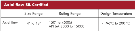
Fluid is channeled into an annular path between the inner and outer bodies until it reaches the characterized cage. Smooth changes in flow direction and no turbulences contribute to lower noise levels. The high capacity, combined with the large range ability, make our axial valve to be acknowledged as the ideal design to control over the full range of process conditions with a single valve.
As an option extended body neck is offered for cryogenic operations, with a variety
of sealing wafer. Zero emission is guaranteed by the O-ring seals combined with back- up packing. Distance between flanges is in accordance with ISA 75.03 when data are available or API 6D for larger sizes. All types of quarter turn actuator are easily mounted. Our model RAX Cv features:
- Larger Cv value, combined with high rangeability.
- Standard at 90° reduced torque actuator.
- No backlash, low friction drive mechanism, with reduced torque requirements.
- Zero stem leakage.
- Cage guided balanced plug for smooth operation.
- Linear, equal percent or other characteristics.
- Effective noise reduction and cavitation.
- Soft seated, bubble tight shut-off.
- Variety of cage designs to handle gas and liquid critical applications.
Further information about Axial Valves is available in Samson Ringo Axial flow valves brochure PRD-VAXL-ING-001-R0.
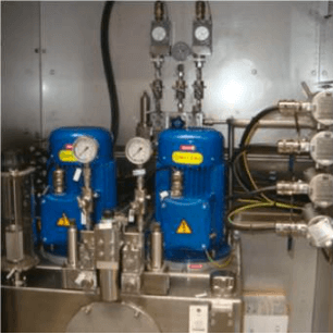
Actuators
Actuators assembled with Ringo valves for the HIPPS systems can be pneumatic or hydraulic and they are supply in full compliance with customer specifications. Actuators include the control panel as specified, with solenoid valves.
Partial Stroke Test is available depend on SIL classification requirements.

FACTORY ACCEPTANCE TEST / SIL CERTIFICATION OF THE COMPLETE HIPPS
Samson Ringo offers full integration of the HIPPS elements in the factory: initiators, logic solver and final elements (valves + actuators + control panel):
- Performance of Factory Acceptance Test of the completely integrated HIPPS. Test can be witnessed by customer or by his nominated Third Party Inspection agency.